nate.co
Well-Known Member
- First Name
- Nate
- Joined
- Sep 1, 2023
- Threads
- 9
- Messages
- 151
- Reaction score
- 313
- Location
- Lafayette, Colorado, USA
- Vehicle(s)
- 2024 Ranger Raptor, Polestar 2
- Thread starter
- #1
I installed an ARB twin compressor using an SDHQ mounting bracket, wiring extension and compressor filter relocation kit. This places the compressor behind the driver's side rear wheel right above the muffler (note this kit is not compatible with the bumper side step option which is available on non-Raptor Rangers). I used the SDHQ mounting kit and cable, but I did my own quick connect install. SDHQ also sells a nice kit if you want to put the connector on the bumper instead. I didn't want to put it there because I used a trailer controller relocation kit.
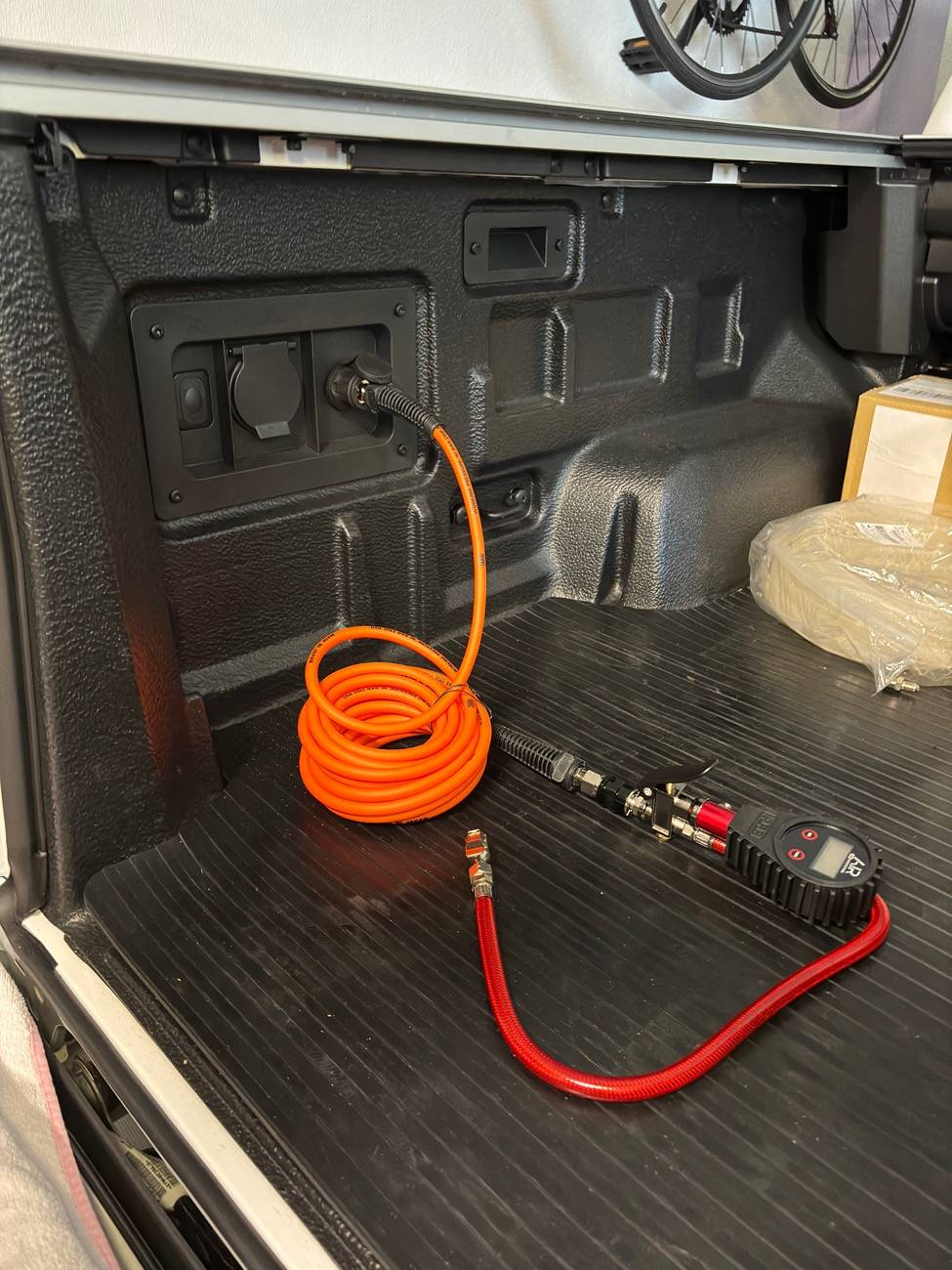
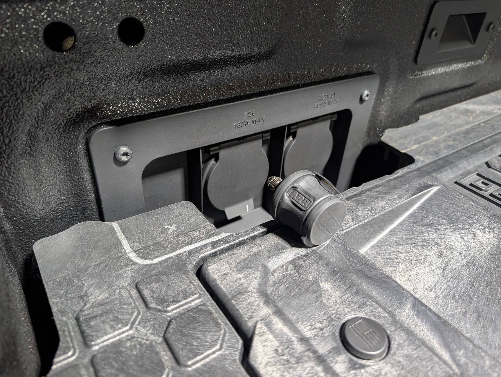
Here's the quick connect in the bed next to the 12v and 110v power plugs. Right under the connector is the rocker switch to turn on the pump.

Parts List
I bought the compressor and other bits from SDHQ as well, but I'm including links to the product detail pages at ARB
Mounting kit
Compressor and plumbing
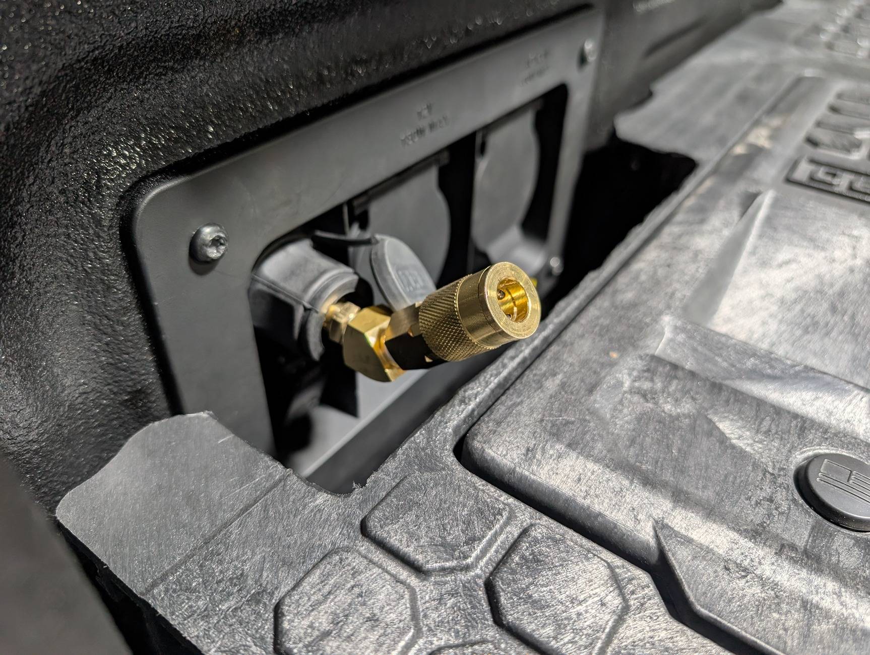
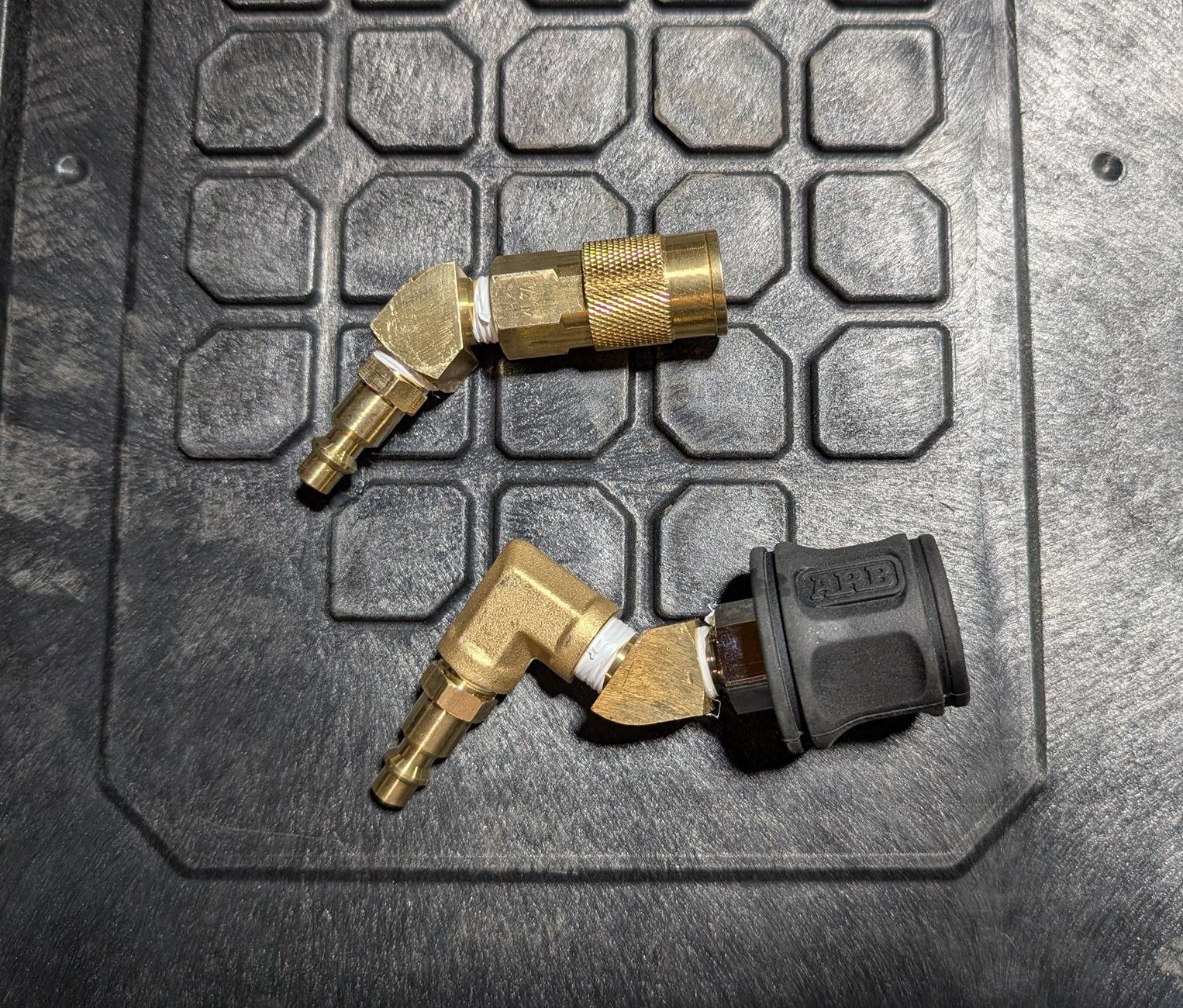
Home made angled quick connect adapter, helps with clearance on the Decked top plate. They make these for pressure washers, but of course pressure washers have a different quick connect than compressors.
Prep for the compressor install
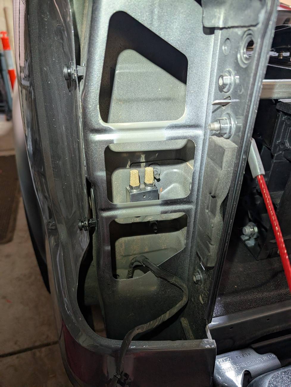
Follow the instructions to install the intake relocation kit which places the compressor input into the side of the truck right ahead of the driver's side tail light. Here it's shown before the two air hoses were run to it.

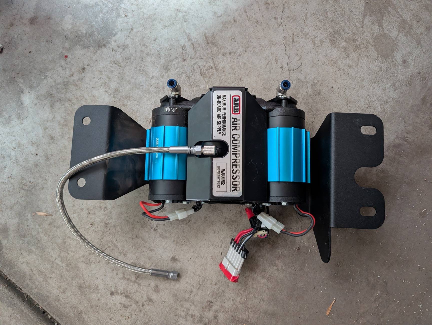
Next, bolt the load supporting part of the bracket to the compressor. There's a steel load support section and separate aluminum heat/debris shields that you install after the compressor is in place. This is part of the bracket instructions, just make sure to use a right-angle NPT to JIC-4 adapter and orient it as shown so the hose fitting is towards the back of the truck, there's not enough room above the compressor to have the hose just come straight up out of the top.
The compressor here also has the intake quick connects on the side. The compressor will be oriented so that the intakes are towards the outside of the truck, the output hose is pointing towards the back of the truck. You don't need to have the hose on when installing, I just did it for this pic. You can reach it through the accessory panel hole in the side of the bed, though it's a little awkward to get the fitting on blind.
For the hose, I used JIC-4 to run the main line because it's supposed to seal better, the threads are only used to compress a cone-shaped fitting that seals and with NPT connectors its the threads that need to seal. Any time you use the NPT connectors, make sure you use teflon plumbers tape on the threads to make sure it seals properly.
To install the compressor, follow the instructions. The printed copy that comes with the bracket and cable are fine, but the PDF versions online have better (high res) pics. I didn't have to remove the exhaust hanger like the instructions suggest, I was able to just maneuver the compressor into place and bolt it up, but it was definitely a challenge getting it into place. Wear eye protection unless you want dust and dirt in your eyes! The compressor is HEAVY so be careful lifting it above your head while installing.
Once the compressor is in place, connect the filter hoses to the relocated filter and put the tail light back in place.
Wire power to the battery
Next, wire the compressor directly to the battery. The compressor has its own relay and a purple signal wire to turn it on. There are two plugs on the compressor -- one large one with all the power and ground lines and then a separate smaller one with the signal line. Running the power cables was a pretty big pain just to find the right route from the battery to the back corner of the truck. The 9 foot extension is the right length, within a couple inches. The instructions with the extension kit are good, you just need to use every bit of the wire and get it tucked into the right spots to make it work.
The extension has wiring for a control switch, but you can just clip off that part of the extension as it's not used in this setup. It would only be used if you want to put a switch up in the cab (and not use the outfitter switches) but I have the switch right below the compressor output so all the signal wiring is right next to the compressor. I didn't re-use the connector or extra signal wire from the extension, I did cannibalize the wiring harness that comes with the compressor itself.
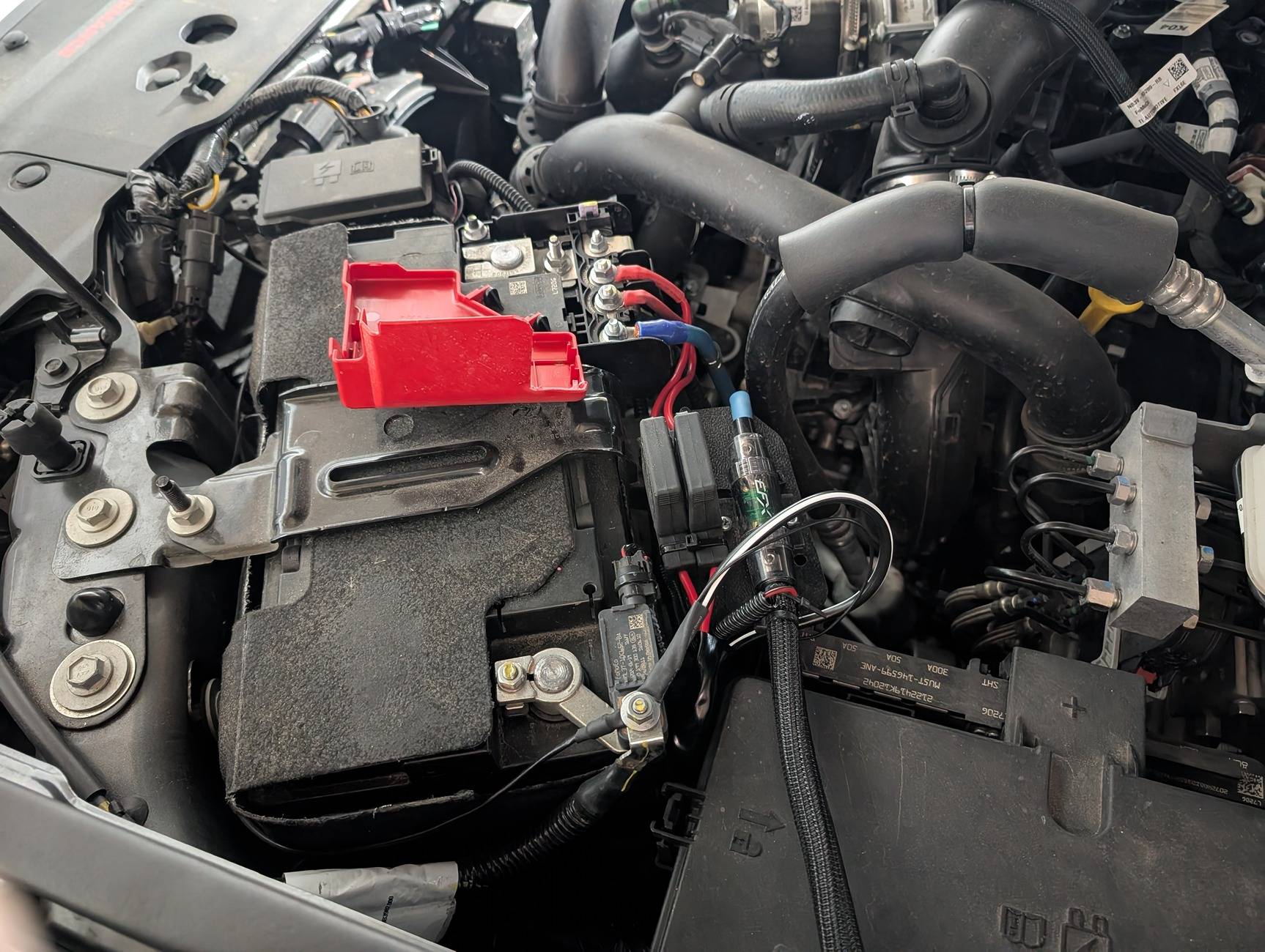
The compressor has two separate main power leads, each with a fuse. I mounted this next to the amp fuse holder I built as part of my audio upgrade.
Install quick-connect and switch
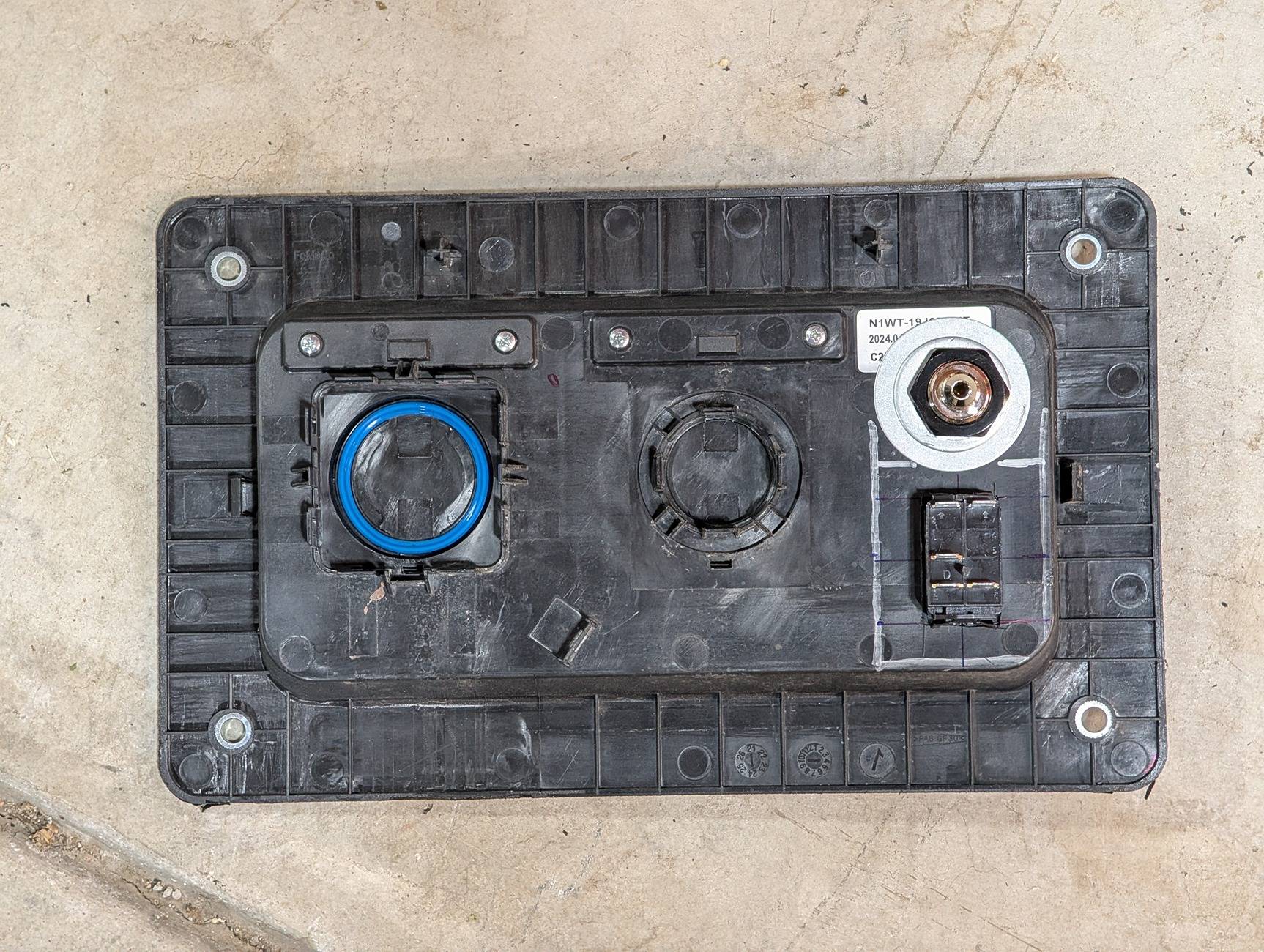
Remove the accessory power panel in the bed and install the quick connect and rocker switch. On the back, I used a washer to give a little more strength to the quick connect mounting point.
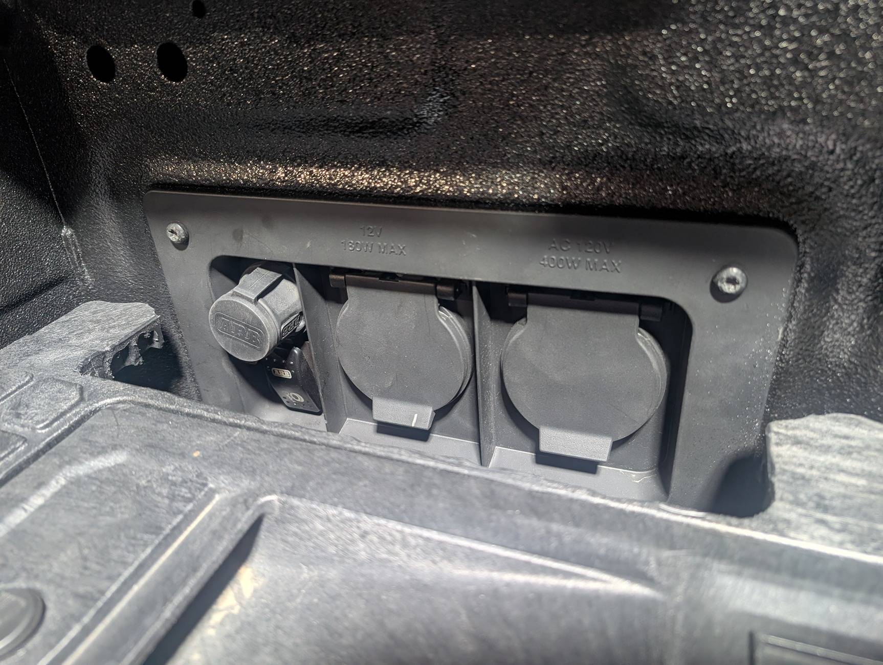
Left to right here: the 110 connector (which has 8 tabs to remove), the 12v connector in the middle (4 tabs) and the quick connect and rocker switch on the right. Make sure you don't over-tighten the nut on the back of the quick connect, if you do it may not release the connector correctly.
Since the wiring here is drastically simplified from what the compressor can be used for (I am not wiring in a reservoir, lockers, multiple switches, etc.) all I need is a +12v supply for the signal line and a ground. I wanted the compressor to only run if the switch is on and if the ignition is on (accessory mode at least).
The 12v connector here is perfect for this, as it only has power when the truck is on, and it's right there. I took the wiring harness that comes with the compressor and just cut off the signal section at the first place the cable splits, then removed the wrapping back to where it splits off to have multiple grounds. This gave me a plug that goes into the compressor, a purple signal wire and three ground wires which is exactly how many you need.
I also picked up a little section of 16g red wire and a pack of "vampire" taps. I didn't really feel like cutting and splicing the 12v socket so I just used these taps, which seem to work fine. I added female blade connectors onto the red wire and two of the three ground wires.
Wiring connections:
Here's a diagram of the switch pinout (stolen from an F150 forum). Battery in this case is the 12v socket and the light is the compressor signal line. I didn't use the bottom-right at all (I think this lights the top of the switch at all times but I didn't want to do that since it's in the bed of the truck, I just want it lit when turned on)

Finishing up
Here is the compressor line and wiring to the accessory panel. I had a 0.3m hose and it's about 2 inches too short, so I went with the 0.5m one, which is plenty long. I cut a two foot section of old garden hose and put the compressor line through it so that the excess compressor line didn't bang or rub against the body of the truck from the inside.
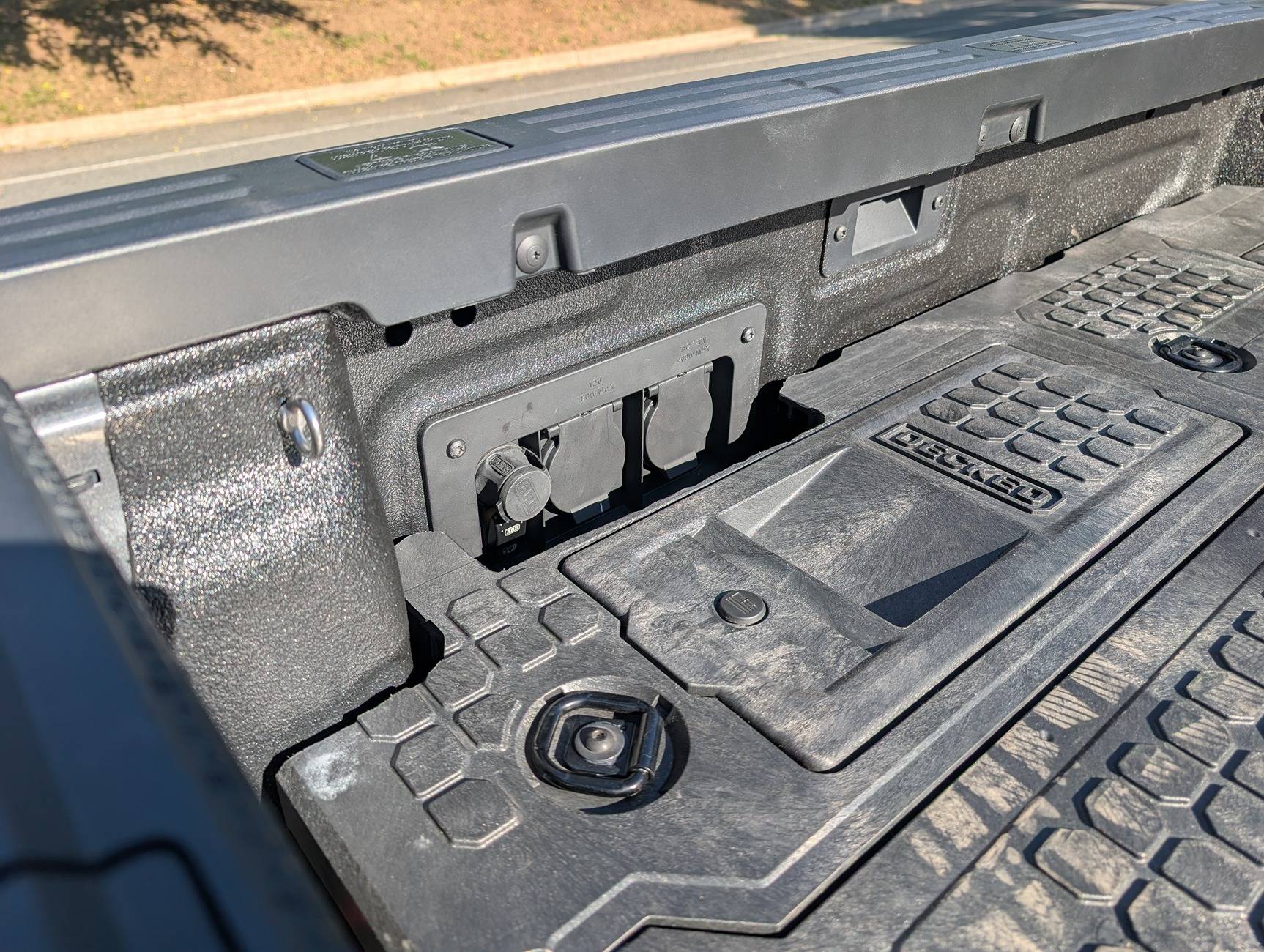
I had to trim the Decked side panel to get more access to the accessory panel, I used a jigsaw to cut it and then a dremel to smooth out all the edges around and do some cleanup.
Here's a better look at the rocker switch after it's all done -- just enough room for the quick connect and the switch.
The hose does connect here, but it's jammed up against the Decked side panel. Because of this I built a little angled quick connect to quick connect adapter using the spare NPT quick connect from the hose kit and some NPT parts I picked up on Amazon. I had enough parts for two, but the all brass one works better.

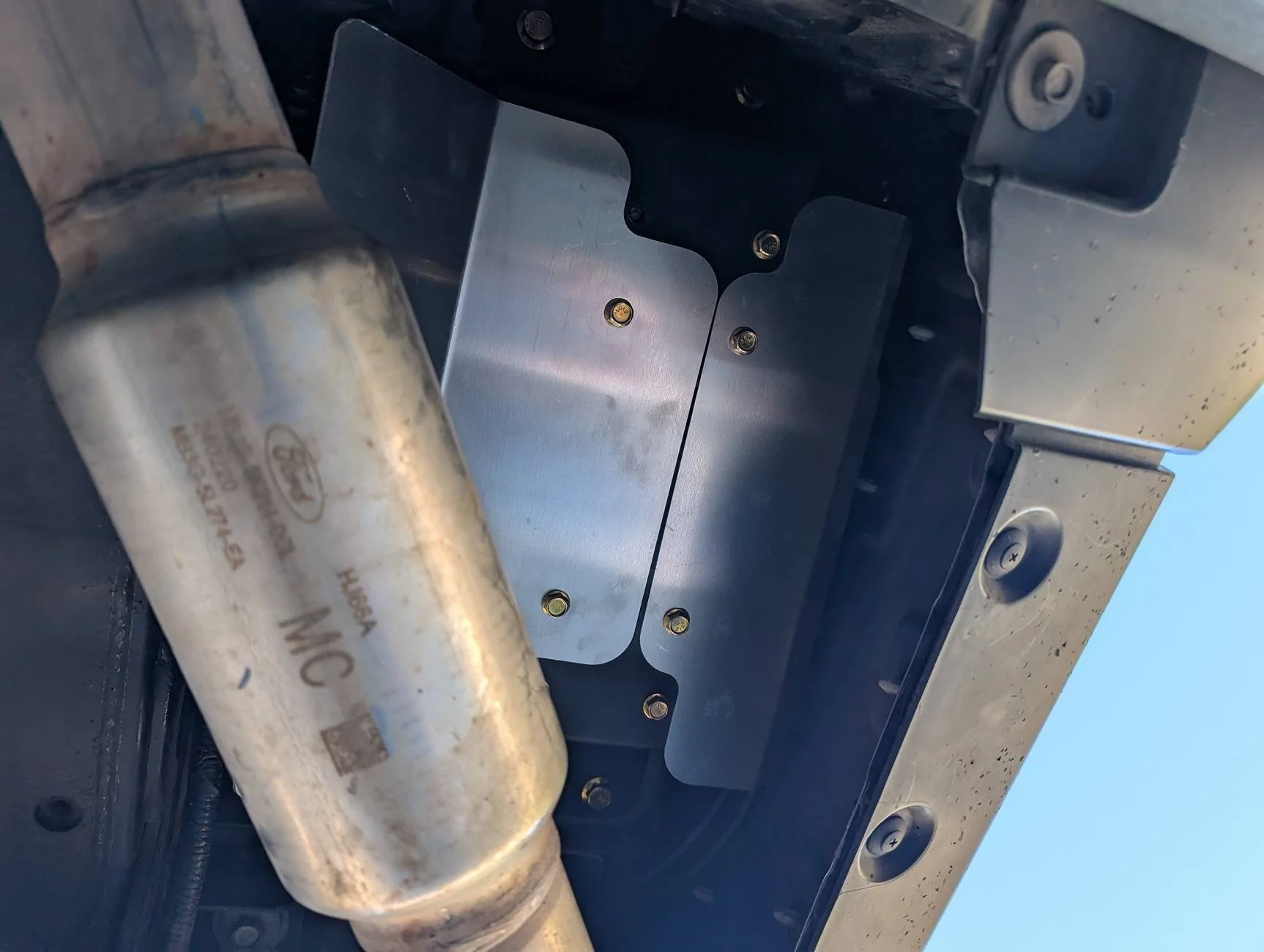
Once all the plumbing and electrical is done, bolt the heat/debris shields onto the compressor and button everything up. Turn the truck on and see if the compressor works -- it should run momentarily and then stop unless you have something hooked up to the output line (there is a pressure cutoff in the compressor). I would always "drain" the compressor when turning it off, too.
There is a missing bolt here (top left in the pic) because I torqued one too much and snapped it off using my crappy torque wrench. I figure 7 out of 8 bolts is probably fine (the compressor manual says you need 4 to have a secure mounting setup). I used blue threadlocker on all the bolts just in case.
Overall, I really like this install. It's totally out of the way, seems very secure and well protected. The connector and switch are nicely hidden away in the bed and looks like it came this way from the factory.
Here's the quick connect in the bed next to the 12v and 110v power plugs. Right under the connector is the rocker switch to turn on the pump.
Parts List
I bought the compressor and other bits from SDHQ as well, but I'm including links to the product detail pages at ARB
Mounting kit
- SDHQ mounting bracket
- SDHQ 9-foot wiring extension (make sure to get the 9 foot one)
- SDHQ compressor filter relocation kit
Compressor and plumbing
- ARB twin compressor
- NOT the new brushless one, at this time the SDHQ mounting kit does not support it because ARB changed the mounting hole pattern
- https://amzn.to/4mJNx0I
- Compressor output elbow with JIC-4 output
- Quick connect with JIC-4 connector
- 0.5m JIC-4 reinforced hose
- Quick connect dust cover
- Hose kit
- https://amzn.to/46QWbVu
- (I only used the hose and the extra quick connect, could have bought those separately)
- Standalone hose
- Tire inflator / deflator
- Blow gun accessory
- Washer I used on the back of the quick connect to add a little more strength
- Plumber's teflon tape for NPT threads
- Vampire taps for switch power and ground
Home made angled quick connect adapter, helps with clearance on the Decked top plate. They make these for pressure washers, but of course pressure washers have a different quick connect than compressors.
- Brass quick connect from Home Depot
- ARB NTP quick connect (part of the above hose kit)
- Brass quick connect
- Right-angle NPT female-to-female fitting
- 45 degree NPT male-to-female fitting
Prep for the compressor install
Follow the instructions to install the intake relocation kit which places the compressor input into the side of the truck right ahead of the driver's side tail light. Here it's shown before the two air hoses were run to it.
Next, bolt the load supporting part of the bracket to the compressor. There's a steel load support section and separate aluminum heat/debris shields that you install after the compressor is in place. This is part of the bracket instructions, just make sure to use a right-angle NPT to JIC-4 adapter and orient it as shown so the hose fitting is towards the back of the truck, there's not enough room above the compressor to have the hose just come straight up out of the top.
The compressor here also has the intake quick connects on the side. The compressor will be oriented so that the intakes are towards the outside of the truck, the output hose is pointing towards the back of the truck. You don't need to have the hose on when installing, I just did it for this pic. You can reach it through the accessory panel hole in the side of the bed, though it's a little awkward to get the fitting on blind.
For the hose, I used JIC-4 to run the main line because it's supposed to seal better, the threads are only used to compress a cone-shaped fitting that seals and with NPT connectors its the threads that need to seal. Any time you use the NPT connectors, make sure you use teflon plumbers tape on the threads to make sure it seals properly.
To install the compressor, follow the instructions. The printed copy that comes with the bracket and cable are fine, but the PDF versions online have better (high res) pics. I didn't have to remove the exhaust hanger like the instructions suggest, I was able to just maneuver the compressor into place and bolt it up, but it was definitely a challenge getting it into place. Wear eye protection unless you want dust and dirt in your eyes! The compressor is HEAVY so be careful lifting it above your head while installing.
Once the compressor is in place, connect the filter hoses to the relocated filter and put the tail light back in place.
Wire power to the battery
Next, wire the compressor directly to the battery. The compressor has its own relay and a purple signal wire to turn it on. There are two plugs on the compressor -- one large one with all the power and ground lines and then a separate smaller one with the signal line. Running the power cables was a pretty big pain just to find the right route from the battery to the back corner of the truck. The 9 foot extension is the right length, within a couple inches. The instructions with the extension kit are good, you just need to use every bit of the wire and get it tucked into the right spots to make it work.
The extension has wiring for a control switch, but you can just clip off that part of the extension as it's not used in this setup. It would only be used if you want to put a switch up in the cab (and not use the outfitter switches) but I have the switch right below the compressor output so all the signal wiring is right next to the compressor. I didn't re-use the connector or extra signal wire from the extension, I did cannibalize the wiring harness that comes with the compressor itself.
The compressor has two separate main power leads, each with a fuse. I mounted this next to the amp fuse holder I built as part of my audio upgrade.
Install quick-connect and switch
Remove the accessory power panel in the bed and install the quick connect and rocker switch. On the back, I used a washer to give a little more strength to the quick connect mounting point.
Left to right here: the 110 connector (which has 8 tabs to remove), the 12v connector in the middle (4 tabs) and the quick connect and rocker switch on the right. Make sure you don't over-tighten the nut on the back of the quick connect, if you do it may not release the connector correctly.
Since the wiring here is drastically simplified from what the compressor can be used for (I am not wiring in a reservoir, lockers, multiple switches, etc.) all I need is a +12v supply for the signal line and a ground. I wanted the compressor to only run if the switch is on and if the ignition is on (accessory mode at least).
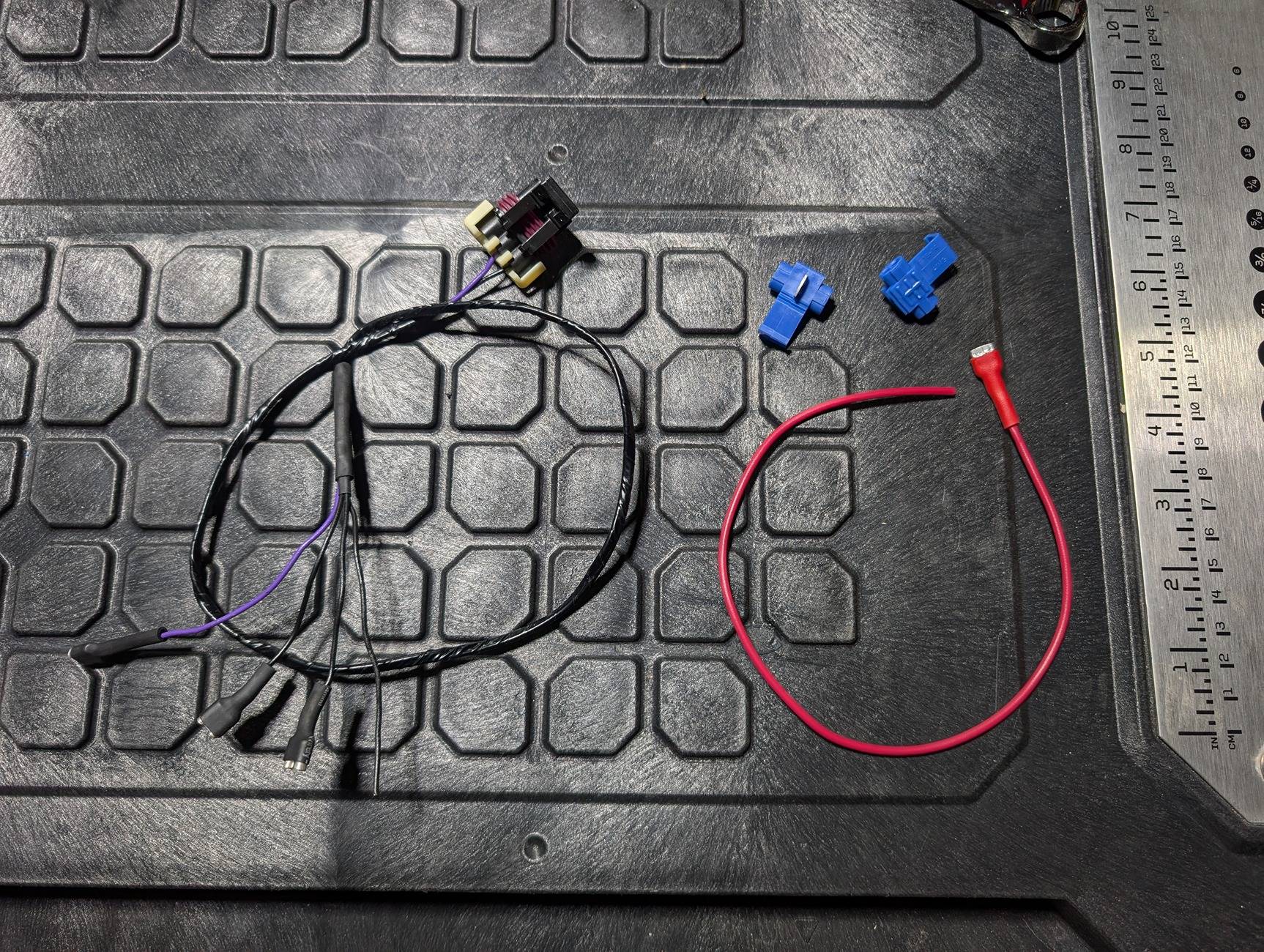
The 12v connector here is perfect for this, as it only has power when the truck is on, and it's right there. I took the wiring harness that comes with the compressor and just cut off the signal section at the first place the cable splits, then removed the wrapping back to where it splits off to have multiple grounds. This gave me a plug that goes into the compressor, a purple signal wire and three ground wires which is exactly how many you need.
I also picked up a little section of 16g red wire and a pack of "vampire" taps. I didn't really feel like cutting and splicing the 12v socket so I just used these taps, which seem to work fine. I added female blade connectors onto the red wire and two of the three ground wires.
Wiring connections:
- The big connector plugs into the compressor
- The bare ground wire will go to the GREEN wire for the 12v socket using a vampire tap
- The bare red wire will go the RED wire for the 12v socket using a vampire tap
- The blade connectors all go to the rocker switch
- Two ground wires to the top two connectors on the back of the rocker
- Red wire goes to the middle connector on the rocker (power in)
- Purple wire goes to the bottom-left connector on the rocker (switched power out)
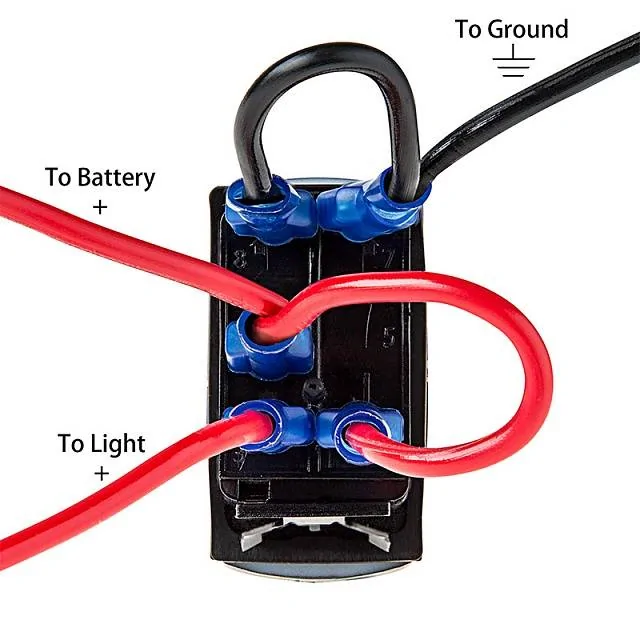
Here's a diagram of the switch pinout (stolen from an F150 forum). Battery in this case is the 12v socket and the light is the compressor signal line. I didn't use the bottom-right at all (I think this lights the top of the switch at all times but I didn't want to do that since it's in the bed of the truck, I just want it lit when turned on)
Finishing up
Here is the compressor line and wiring to the accessory panel. I had a 0.3m hose and it's about 2 inches too short, so I went with the 0.5m one, which is plenty long. I cut a two foot section of old garden hose and put the compressor line through it so that the excess compressor line didn't bang or rub against the body of the truck from the inside.
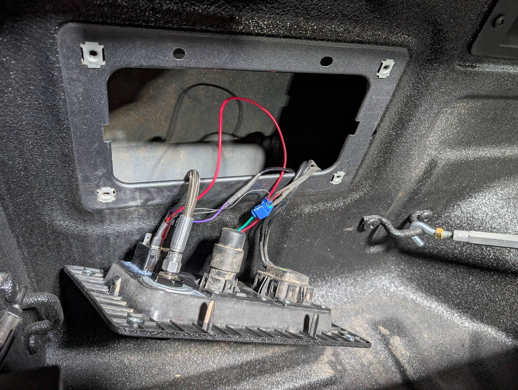
I had to trim the Decked side panel to get more access to the accessory panel, I used a jigsaw to cut it and then a dremel to smooth out all the edges around and do some cleanup.
Here's a better look at the rocker switch after it's all done -- just enough room for the quick connect and the switch.
The hose does connect here, but it's jammed up against the Decked side panel. Because of this I built a little angled quick connect to quick connect adapter using the spare NPT quick connect from the hose kit and some NPT parts I picked up on Amazon. I had enough parts for two, but the all brass one works better.
Once all the plumbing and electrical is done, bolt the heat/debris shields onto the compressor and button everything up. Turn the truck on and see if the compressor works -- it should run momentarily and then stop unless you have something hooked up to the output line (there is a pressure cutoff in the compressor). I would always "drain" the compressor when turning it off, too.
There is a missing bolt here (top left in the pic) because I torqued one too much and snapped it off using my crappy torque wrench. I figure 7 out of 8 bolts is probably fine (the compressor manual says you need 4 to have a secure mounting setup). I used blue threadlocker on all the bolts just in case.
Overall, I really like this install. It's totally out of the way, seems very secure and well protected. The connector and switch are nicely hidden away in the bed and looks like it came this way from the factory.
Sponsored
Last edited: