
spack
New Member
- First Name
- chad
- Joined
- Oct 2, 2024
- Threads
- 0
- Messages
- 1
- Reaction score
- 6
- Location
- chester springs pa
- Vehicle(s)
- 2018 ford raptor
- Occupation
- physycist
While this article explains what the cam phasers are and that there is an issue, it does not explain why there is an issue. Is this a quality problem? Is there some revision issue? Is this an issue at assembly?
While this article explains what the cam phasers are and that there is an issue, it does not explain why there is an issue. Is this a quality problem? Is there some revision issue? Is this an issue at assembly?
This is copied from a post I did on the raptor Forum called phasers: From the Top. I've tried to shorten it a bit. It's still long winded and yet there is more to say. In short I believe this is the closest I've seen to actually identifying the root cause
The basics:
Cam phasers alter the position of the camshafts relative to the crankshaft and thus when intake and exhaust valves open and close relative to the piston positions. Without phasers this relationship is fixed, which is how things used to be. Phasers alter when fuel/air starts and stops entering on intake, and when exhaust starts and stops exiting on the exhaust cycle. Changes to the camshaft’s position relative to the crankshaft wouldn’t be necessary except for a couple of qualities of air. It’s springy (compressible), and it has mass. Basically it resists movement when stopped and once moving, it resists stopping. And these characteristics change based on temperature and pressure. Even if the characteristic of air didn’t change, as engine RPM increases, the time air takes to enter and exit the combustion chamber is more or less bounded. But the time allowed for entry and exit gets smaller with higher engine speed. Delay of air movement becomes a bigger percentage of the engine cycle at speed. Throw in a turbo charger, and you have another variable that influences how the air moves and how long it takes. Change exhaust headers, and the exhaust exit time changes. There becomes a nearly infinite set of timings for optimum performance. And one persons performance may be a California dude’s pollutant. The cam phaser is one very limited way of dynamic tuning to achieve some set of performance goals. I say limited because there are many more things we could do with valves than decide when they open and close; how far they open for example. And with a phaser, if you open a valve sooner, you also close it sooner. What if we wanted to open it sooner and close it later (duration). Can’t do that with a phaser. But a phaser is an amazingly simple device that allows the camshaft relationship to the crank to be controlled. Unlike air, oil is not compressible. The cam phasers used on most modern cars use oil pressure to turn the camshaft back and forth, through a limited range, inside the camshaft sprockets. By pushing oil into one chamber (or set of chambers) in the sprocket, the camshaft itself can be pushed ahead (advanced) past its current position relative to the sprocket and thus crankshaft. By pushing oil into an opposing chamber we can push the camshaft behind (retard) its current position. If no oil is allowed in or out, the camshaft stays glued to the sprocket. And that’s all there is to the basic device. A couple of oil ports in and an exit or drain port out. Oh and there is a locking pin, sigh…. To take care of startup when there is no oil pressure.
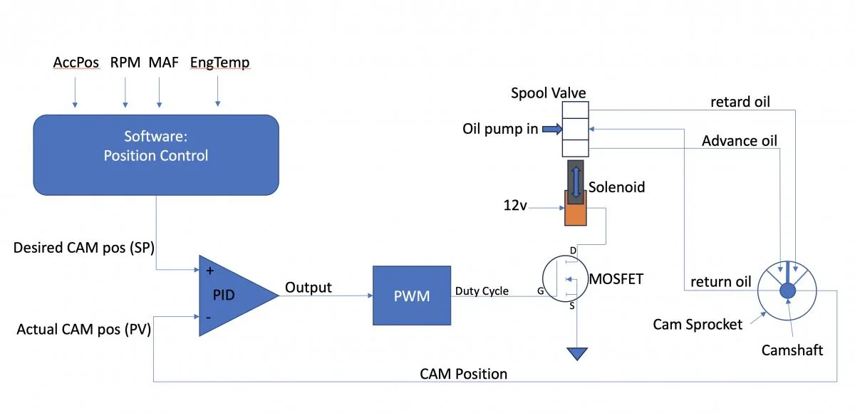
The control system is detailed in the drawing at the bottom of this post.
At its core is a PID, which stands for Proportional Integral Derivative controller. The PID represent closed loop control. Its purpose in life is to keep its 2 inputs as close together as possible. One input, the desired camshaft angle, which is the SetPoint(SP) in PID lingo, comes from software which uses all sorts of other inputs to decide what the cam angle ought to be. The other input, the actual camshaft angle, which is the Process Variable (PV) in PID lingo, comes from a position sensor on the camshaft. The PID assures that whatever the software wants, the software gets. PIDs are everywhere in car control. Cruise control is PID controlled. The Setpoint being what you set the road speed to, and the ProcessVariable, coming from the same sensor that drives the speedometer. The output of the PID drives the accelerator pedal. If you encounter a hill and the car starts to slow, the PID output increases, producing more engine power, until the speed increases. In the camshaft case the output of the PID is converted into a pulsed output, which drives a field effect transistor, which drives a solenoid, which drives a spool valve, which drives oil into and out of the cam phaser, which drives the cam’s position relative to cam sprocket, and ultimately relative to the pistons position. A bit more on that later.
So here we go with more Ford specific stuff….
On start up and idle…
The Exhaust Phaser’s default lock position is fully advanced.
The Intake Phaser’s default lock position is fully retarded.
Why those are the default positions is not the focus of this post. That’s what they chose.
From a control point of view, the above has implications as follows. By arbitrary definition, advancing camshaft timing is always decrementing in degrees and retarding is always incrementing, for both exhaust and intake cams. Again arbitrarily, 0 degrees is always the lock position in both. So in the exhaust case the numbers will start from 0 degrees (locked) as the most advanced position and increment from there to retard. The numbers are never in the negative range. Intake also starts from 0 (locked) but as the most retarded position. From there the numbers go negative to infer more advance. The numbers are never positive. These are indeed arbitrary definitions but cam position will be reported this way by an ECU monitoring and configuration tool like Forscan. They are also the language the PIDs speak.
Solenoids are electrically actuated devices used to control the oil valves that influence oil flow to the chambers within the camshaft sprockets. Just like the lock pin position has implications to the positional definitions, these starting positions also have implication relative to the control solenoids and what the PWM duty cycles mean. PWM stands for pulse width modulation and refers to the electrical signal that the ECU feeds the solenoid to control it. It’s measured in percent and is another informative variable one can see with Forscan. At a minimum it tells us what the ECU and thus the PID is trying to tell the solenoid to do; like advance, retard, or hold steady. From a control standpoint, an unpowered solenoid should match the lock positions. An unpowered solenoid is by definition, 0% duty cycle. The phaser default lock positions imply that duty cycle means something different between exhaust and intake. 0 duty cycle means full advance for exhaust because that is where the exhaust phaser is in its default position. Incrementing duty cycle form there must mean to retard. Conversely, 0 duty cycle means full retard for intake. Increasing duty cycle from there must mean advance. This brings the locked positions into agreement with an unpowered ignition system about to start and it brings percent duty cycle in agreement with which direction exhaust and intake can go from their respective home positions with increasing duty cycle or increasing PID output.
A little bit more on Solenoids: Control of the oil into the advance and retard chambers of the phaser is controlled by selecting oil pressure to one side or the other through a spool valve. The spool valves turns linear shaft valve movement in or out, into selection of the phaser chamber to push oil into and allow oil out of. A solenoid creates the linear force into the valve, and a spring returns the valve when that spring overpowers the solenoid. The higher the duty cycle the greater the force. A solenoid is a variable force actuator, not a linear position actuator. Therefore a particular duty cycle does not imply an exact oil flow in either the advance or retard directions except at extremes or relative to something else. In fact the implementation of solenoid control will not be designed such that 100% duty cycle is legal. From a Forscan point of view, percent duty cycle is a magnitude reference but other than low duty cycles and high duty cycles, you can’t really infer advance, holding, or retard directly. You can determine, from looking at whether advance or retard angles are changing or not, as to what the holding duty cycle might be, and once that is known you can determine advance or retard intention and with what relative magnitude, by using the holding percentage as your reference. In other words, is the duty cycle above or below the holding reference and by how much?
The lock pin. At engine start, the lock pins hold the camshafts in their 0 degree, default positions; max advance for exhaust and max retard for intake. After startup, the ECU decides when to unlock them. Certainly after there is sufficient oil pressure to do so. How is the lock-pin unlocked given these starting points? The lock pin eject is a parasitic action in this architecture. Most car manufacturers who default lock at one extreme or the other, don’t have independent lock pin control and the complexity that might bring. Instead the architecture uses a method which is dependent on the starting position. With exhaust, since we start from the lock position as the most advanced position, it is the action of retarding oil pressure which will eject the pin. Thus there is a small oil channel from the retarding chamber that feeds the lock pin well. As the Solenoid receives its first command to retard, oil pressure which is meant to cause retarding action also pushes the lockpin out of the well. With intake, since we start from the lock position as the most retarded position, it is the action of advancing oil pressure which will eject the pin. Thus there is a small oil channel from the advancing chamber that feeds the lock pin well. As the Solenoid receives its first command to advance, oil pressure which is meant to cause advancing action also pushes the lockpin out of the well. In both cases there is a little bit of a battle going on between the pin going upward out of the well to unlock, and the advance or retard action creating a shear force on the pin and against the lock pin well, fighting the lock-pin’s upward movement out of the well. This is a source of wear on one side of the lock pin well; the side away from the default position. It is an architectural feature and quite frankly, a weakness. The telltale sign of this wear is a smoothly ramped well pin hole rather the a sharp cylindrical hole. Once sufficiently warn, the pin will no longer lock the cam and sprocket together. This is particularly apparent if the engine has been sitting long enough for oil to have drained out of the cam sprocket chambers. With no locking capability the camshaft bounces back and forth from one chamber limit to the other before oil pressure builds enough to allow PID control of cam position.
The phasers have bias springs. The springs bias the camshafts towards the advance direction. How those are calibrated I don’t know but probably against the aggregate force of driving the cams against the valve springs. The intent would be to make the oil pressure required to advance, similar to retard. There is an asymmetry in that they would help the exhaust cam head to the home position and pin lock on engine stop. But not for intake. This is probably immaterial. But the point is, they are not “parking springs”.
The difference between the MLZ and HL3Z…-CD parts….
There has been lots written about Ford’s cam phaser problems…. As though it’s a Ford issue. Try Googling CAM RATTLE followed by the car manufacturer of your choice. Toyota, Honda, Hyundai, the list goes on. You won’t come up empty. It has a lot to do with the fact that almost everyone has a phaser related to the same patent, and that patent is to do with the lock pin ejection method when using a vane and chambers phaser as discussed in this post. There is also information on this forum that says you need to have the MLZ parts to have permanently fixed the potential phaser issue. I originally question that for the following reason. But my mind has since changed as I’ll note later. Every picture I have seen of a failed HL3Z part is version -CC or earlier and the CD parts have an interesting change. Having said that, there are differences between the MLZ part and the HL3Z … -CD parts. They are NOT architecturally different. In other words, lock pin ejection is still linked to exhaust retard or intake advance and the force battle that architecture creates against the lock pin well sidewall. What is different comes down to 3 things, The MLZ part has more depth axially than the HL3Z parts which means the advance and retard chambers have more volume and create more advance or retarding torque in the MLZ parts given the same oil pressures. Although this is somewhat offset by the fact that the chamber diameter across is less than the HL3Z parts. The bias spring constant on the MLZ part is higher. The second difference is in how the lock pin well is fed with oil to eject. In the MLZ part, the channel that feeds the well is in the vane and not in the well plate. The well sits by itself with no channel directly connected to it. The third, and I think, key difference is in the other end of the locking pin where the locking pin spring is anchored. Both designs hold the return spring centered with a plastic cap/pin. In the HLZ part this plastic cap rides on the back plate of the phaser. This backplate is in nearly constant motion relative to the cap. In some failed parts, this plastic cap can be seen to have disintegrated. If that happens the spring can become entirely misaligned and not able to seat the locking pin in the well with sufficient force. This will in turn cause the pin not full engage and further well wear occur as it pops loose. In the MLZ part, this plastic spring cap is not in contact with a moving plate. That is potentially huge. There is also an immaterial visual difference between the HLZ and MLZ parts, There is a bias spring cover which is press fit on the MLZ parts. This serves to keep the bias spring in place because the studs the springs anchor to, don’t have capture heads like the HL3Z parts. The HL3Z -CD parts are distinctly different than their earlier counterparts in how the lock pin well is constructed. Previously the well did not have a sidewall where the oil channel fed it. Now it does. So presumably, less oil pressure will float the pin and the pin is more symmetrically supported when in the well. But the overall architecture between both phaser types is unchanged. If the plastic cap is not the issue, and the below referenced patent is, the the latest HLZ-CD part will address the problem. If the cap is the problem, the HLZ part will not fix the problem. I have see one failed instance of the latest HLZ part failing because of the plastic cap.
On the subject of the lock pin architecture, the following patent https://patents.google.com/patent/US20050188933A1/en refers to an improvement over prior-art and that prior-art is the Ford design and Toyota design and everybody else’s design. They claim the prior method is prone to trouble because of the shear force versus ejection force mentioned in this post. Their solution is to feed the lock pin well from both retard and advance chambers thus allowing the solenoid to dither and feed both wells at the same time to cause pin eject. This results in overall well pressure without advance or retard torque, leaving only the lock pin to experience ejection pressure. After unlock the phaser can be advanced or retarded, avoiding the shear force on the pin well. This patent is quite elucidating in that it appears to be well known in the industry that the prior-art has a very specific flaw that creates a problem just about every car manufacturer has seen to one degree or another. Yet the industry has been focused on making the prior-art work for longer, rather than addressing the root cause.
Although this is possibly the cause of the Ford EcoBoost issue, I think the primary cause is loss of the lock pin's plastic return spring cap due to wear on an initially not well lubricated, moving surface.
Sponsored
Last edited:
